RADley Brains and Controls
 Onboard will be a standard
Arduino Mega2560 mounted in the upper base as noted. I have a cheap one left
over from messing with 3d printer stuff and they seem quite powerful. I've tried
using multiple ProMinis in the past to increase brain power and that was just
too messy. This should give enough horsepower, pins, and be easy enough to code
to drive multiple sensors, motors, gyro/accel, interrupts, servos, and serial
ports without issues.
Onboard will be a standard
Arduino Mega2560 mounted in the upper base as noted. I have a cheap one left
over from messing with 3d printer stuff and they seem quite powerful. I've tried
using multiple ProMinis in the past to increase brain power and that was just
too messy. This should give enough horsepower, pins, and be easy enough to code
to drive multiple sensors, motors, gyro/accel, interrupts, servos, and serial
ports without issues.
Current plans called for mounting the Mega in the Upper Base of the platform and running an old hard drive ribbon wire run up inside the body for connections keeping wiring as clean and organized as I can. A header will be used like an old IDE hard drive connection to connect the two. We will still need larger wires for +5V and Ground and the arms and waist motors but ribbon should run all the sensors, LEDs, etc. Otherwise I plan on running normal three pin Signal/5v/Gnd runs for other sensors on it's own or a Mega shield, and still may jump from the header connector to three pins for some needs.
Power
Powering the platform is a standard RC vehicle 7.2 or 8.4v NiCad or Lipo battery pack or packs. The full voltage will drive the motors while a 5v regulated supply will drive the rest of the sensors, outputs, controller, etc. However, any ADC sensors should use the Aref voltage to make sure ADC readings are correct so not sure how to distribute that, likely in the ribbon cable as there shouldn't be a lot of current required.Since the Mega2560 has a vReg onboard and uses 7-12v power it will likely be powered directly from the switched battery power. I will likely need a separate 5V regulated supply to cover all the various sensors that will be driven especially the multiple sonar devices that I believe use a bit during pings.
Input Sensors
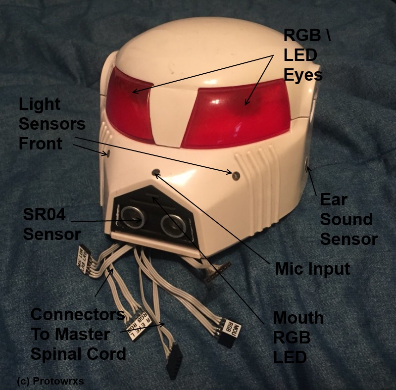
RADley will be loaded up with quite a few of the normal sensor you see on a hobby robot. There may be a few more sonar sensors to try to keep from running over things but generally he will have distance (sonar), light levels, sound levels, orientation information, GPS, compass, IR and maybe a few more.Sonar
Three (3) sonar sensors in the front base, one forward, one left, one right, should be able to see most LOW objects that may be in the way including steps, etc. This does NOT solve problems with higher up things as RAD is taller than most bots I've built. These will all be run in single pin mode to save pins.
There may be two or more units on the shoulder area where the LEDs used to be aligned vertical to allow seeing things higher up. Since RAD can tilt at the waist, this could be useful for finding items in front at higher levels and with two it could be used to follow or hone in on something using differential values. Or another option is to make a new mouth piece and mount one sonar there that can see objects as well as allow scanning around for objects, still debating on that.
There should likely be at least a single rear facing sonar in the base to keep from backing into something and getting stuck but it could have been bumpers or similar as well. I've decided to put a smaller servo I have in the old battery location on the rear to allow scanning on the back side and if done right I'll end up with a printed little "tail" that could be wagged if desired that houses the sonar.
Should there be a downward facing sonar up front to detect drop offs? Might be good idea but how and where? Yet another pin and sensor to monitor? Might be a later add.
Gyro/Accelerometer
I'd like to run a single gyro/accel in the body so he can see how far he is tipping over forward and/or level. This would be better in the body than the head as I'd like to get the head turning by servo or stepper motor. This could be mounted on the arms but that would seem to be a noisy place? Could use an MPU6500 to make everything easier I guess?Light Sensors
Two 5mm Radio Shack "ambient light sensors" will be used a light level sensors as they seem to work and look better as small clear points instead of old looking LDR devices. Need a left and right as always but I am also adding a third rear to be able to better locate light sources or brightest/dimmest areas.Actually the way the third light sensor is mounted in the top/rear portion of RADley's head, it can also be used to trigger being "petted" if the sensor is interrupted in a regular basis from light to dark. Of course that will take some coding to make it right but it's a possibility.
WII Remote Sensor
I have one of these that is yet unused and it would seem to be a great charging base direction finder. By having a couple strips that could connect to the battery like the old laptop bot I built years ago it could find the base using the WII sensor, hone in and then use a switch or sonar to finalize the dock to charge itself. This could be either by command or by battery voltage sensing.Microphone(s)
I am still trying to figure out how to get audio directions from two mics on a device but it would be easy enough to add to the head in some manner on left/right sides by the existing antenna. It would be too difficult to try to embed them in the antenna but next to them in the front should be possible. I am adding a third rear microphone as well to better be able to locate sound sources... I think at least.Compass
A compass will really be needed to assist with any dead reckoning navigation and orientation management. It needs to be up high but how to get up high and still get away from motor noise and NOT on the rotatable head? Or do we put in the head and then just offset based on servo position or angle? Yet to be determined.GPS Sensor
A GPS sensor could be useable to provide for general inside area location but there would be no detailed location abilities without additional feature sets and sensors. Up side it's really easy to deploy and could be mounted in the head as well. Since it's just a serial stream to decode it could keep updating normal lat/lon/alt/direction that could have some uses.PIR Sensors
I'd really like RADley to know if there is movement in his environment so one or more PIR sensors will be used. The challenge up front is I'm not sure where to mount them. I believe they will end up in one of the slots from the chest LED areas, likely the top one, but am still not positive that is the best location. By having two it may be possible to determine which side the motion first occurred but with the limited separation that may not be useable either. In any manner, he need to know motion occurred and be able to act and/or report that back to the PC side for use there.
Voice Commands
RADLey will have an on board bluetooth speaker and microphone linked back to a PC for voice control, talking, and other voice/sound interactions. I think this will work although I'm sure sure onboard audio and electronic noise may be a major issue in regard to this. I've tested this using a super cheap $8US Bluetooth "Shower" speaker/mic combo and it works, just not as good as a directly connected mic. So I may be yelling at RADley more than I really should be, hopefully he, and the neighbors, won't take too much offense to that.
Outputs and Actuators
Output wise is similar to inputs in that RADley will have some standard outputs such as servos, LEDs, sounds, and motion / motor controls.Speech Speaker / Mic
A bluetooth speaker / mic will be in the head that will connect to a related PC for voice commands and voice output. The speaker should be mounted near the mouth area of the robot to allow a more natural sound output location.Sound Effects Speaker
I want to keep another speaker in the head somewhere that can be driven like my other bots for sound effects, noise, etc. Simple single pin driven solution but I can't use the BT speaker so this will be mounted in the head as well. I may just try sharing the same speaker if possible as that would be the cleanest installation.RGB Eyes
RGB Mouth
One (or more) RGB LEDs will drive the mouth output off of one pin like the black head bot I created. This allows mouth color changes as well as eyes for mood options and can be blinked while talking. As noted above, these will be standard LEDs to allow modulation during sound output.
Communications
PC <-> RADLey
Plans are to use simple bluetooth or similar serial module to talk between PC and Arduino. That has worked on previous Head Bot builds under testing and should be ok. For voice control there will be a bluetooth speaker and mic combo as noted before in RADley's head. This will allow talking "to" the robot but the PC will be processing the voice commands, speech, internet access and overall commands to the robot. Bluetooth range will be limited but still better than nothing. Using a laptop can help provide some mobility options for voice commands and PC integration.
IR Receive / Transmit
RADley will have at least one IR receiver on him as it's likely voice command will be somewhat sketchy with all the noise going on and round the robot. An old IR remote will be dedicated to his use and I'll likely label the keys for my uses.I also hope to have an IR transmitter LED on RADley to send information or control devices. Mainly to allow commands to turn on the TV but could be used for other items as well or to control other robots I have that have IR receivers on them. Just a thought and longer term piece right now.