RADley Platform
The platform is a late 1990's RAD 2.0 toy robot. I now have three of them and had started hacking on this one in the past but never took it to the next level. Nice thing about using a RAD is well, it LOOKS like a robot. It also has a nice (but noisy) tracked drive system, can tilt it's waist forwards and upright, and has a pair of arms that can open and close. The head looks pretty cool with the antenna sticking up like ears and he has a dog like appearance.I've had a couple of them since 1999 and picked up another one in 2015 for $32US shipped so I'm not adverse of making at least one of them into a hacked up mobile platform. I do plan on keeping him rather stock looking though and not cut up as I've alway liked the basic appearance of the 2.0 versions.
Platform Design
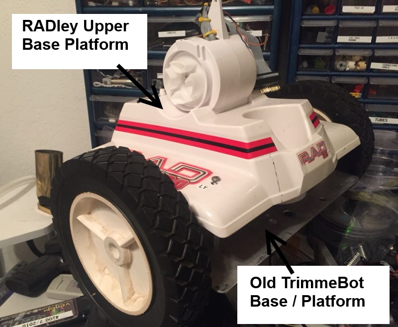
I've broken the basic platform design down into four pieces: 1) the Base, 2) Upper Base, 3) Torso, and 4) Head. By planning ahead with these known pieces I hope to allow easy assembly and disassembly and have a stable platform as well.The Base
Updated 12/2016
 In December 2016 I wanted to get the old LTBot/TrimmerBot/GPS attempted bot off my
bench when I suddenly realized this would actually be a great base for RADley.
This resolves the issues with the loud plastic gearboxes and other problems with the track drives.
Yeah, it looks a little differnt but I think it will work much better. Hopefully at least.
The Base is the very bottom of the robot that houses the drive motors,
tracks, battery pack(s), the H-Bridge for the track motors and possibly the
H-Bridge for the waist/arm motors although this may get moved up into the torso.
In December 2016 I wanted to get the old LTBot/TrimmerBot/GPS attempted bot off my
bench when I suddenly realized this would actually be a great base for RADley.
This resolves the issues with the loud plastic gearboxes and other problems with the track drives.
Yeah, it looks a little differnt but I think it will work much better. Hopefully at least.
The Base is the very bottom of the robot that houses the drive motors,
tracks, battery pack(s), the H-Bridge for the track motors and possibly the
H-Bridge for the waist/arm motors although this may get moved up into the torso.
The Upper Base
 The Upper base is the top cover/shell of the actual base.
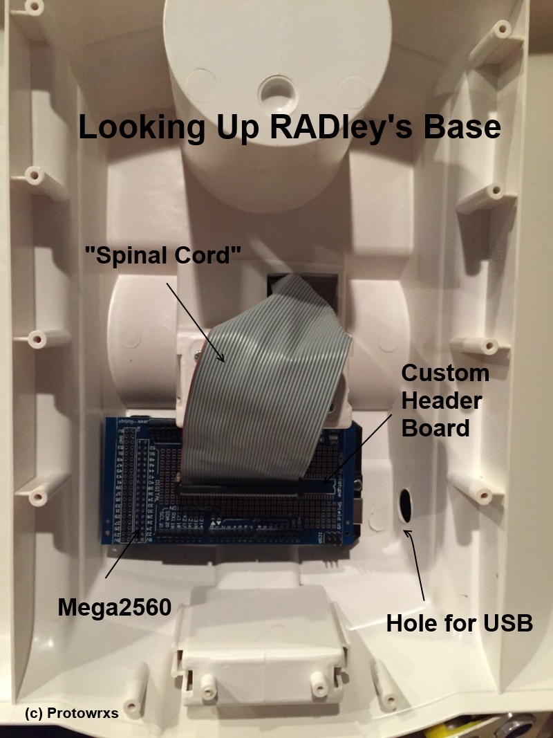
I mounted the micro controller in here for a few reasons. One is there is space
in the hump behind the torso mount,
The Upper base is the top cover/shell of the actual base.
I mounted the micro controller in here for a few reasons. One is there is space
in the hump behind the torso mount,
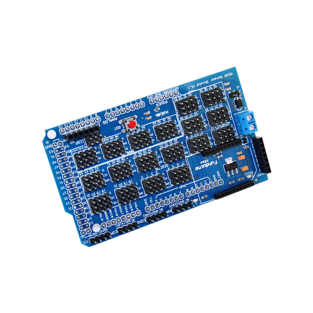 Update 2/2017: Instead of working soldering up a big connector on the Mega shield, I will be using the Mega Sensor shield as shown here.
This does force more wiring and some potential issues with connections, BUT allows flexibility to wire up the spinal cord, torso, or either base with or without using the +5v and Ground signals.
I can now mix and match these and move things around much eaiser than using a dedicated soldered 40 pin connector. I'll use double male pins in the ribbon connector and jumper then as needed.
Update 2/2017: Instead of working soldering up a big connector on the Mega shield, I will be using the Mega Sensor shield as shown here.
This does force more wiring and some potential issues with connections, BUT allows flexibility to wire up the spinal cord, torso, or either base with or without using the +5v and Ground signals.
I can now mix and match these and move things around much eaiser than using a dedicated soldered 40 pin connector. I'll use double male pins in the ribbon connector and jumper then as needed.
The Torso
The Torso mounts to the Upper Base by a handy clip/screw mount that holds the waist tilt mechanism. The Torso contains this waist mechanism as well as the arms mechanism. Once these two parts are together there isn't as much room as I had imagined inside so getting the wiring in the correct spot is rather critical.The Head
Just like a human head, RADley's head contains most of his sensors as you'll see below. Since the head can be removed and manually rotated it needs a wiring connector as well. His head will be the primary focal point for interaction and sensing and will have a lot of wires to connect down the base.Connections and Wiring
I would like the wiring on RADley to be modular enough to allow disconnecting his head or base without having to disconnect a lot of different individual connectors. There is a balance between too many connections and not enough flexibilty that I hope to find.The Head
RADley has three pieces to his head, the upper skull, middle core and the head base.The upper skull contains the rear light and sound sensors and the bluetooth wireless module and possibly the compass module. The compass may need moved to avoid any RF from the BT serial module.
The middle core contains the WS2812 eyes, the RGB LED(s) for the mouth, left and right light and sound sensors, bluetooth mic and speaker, the nose ultrasonic sensor,
The head base attaches to the torso and upper and lower head portions attach to it. It is assumed the head base will not be removed as often as the top pices may. The head base contains the speaker for the Bluetooth speaker connection.
If I can have a single 25pin connector along with a power connector that would allow disconnecting the head from the torso that would allow the desired flexibility.